
- Call Us:
+66(0) 2 730 6500
- Email:
info@brasten.com
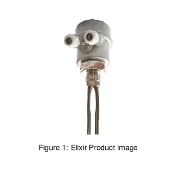
Vibrating Level Switch Manual
Introduction
- Fast and Easy Installation
No Calibration. - No effect of electrical properties of the Service material
High Reliability. - Suitable for highly dusty environment.
- Suitable for grain size up to 20 mm.
- Field selectable operation logic.
Can be configured either for High or Low-Level point switching.
Operating Principle
A specially shaped tuning fork is kept vibrating using piezo-electric elements. Typically, the fork vibrates at its natural frequency. The frequency of oscillation for the tuning fork changes when immersed in liquids. The change in frequency is detected by the microprocessor leading to a switching decision.
Features
- Universal Power Supply: 18-55V DC, 90 – 265V AC.
- Low Power Consumption: less heat, long life
- High temperature durability (H1 up to 200°C)
- Immunity to spurious external vibrations, material turbulence and flow.
- Suitable for liquids with viscosity up to 10,000 cP
Fast switching. - Self-diagnosis
- Independent of materials electrical properties
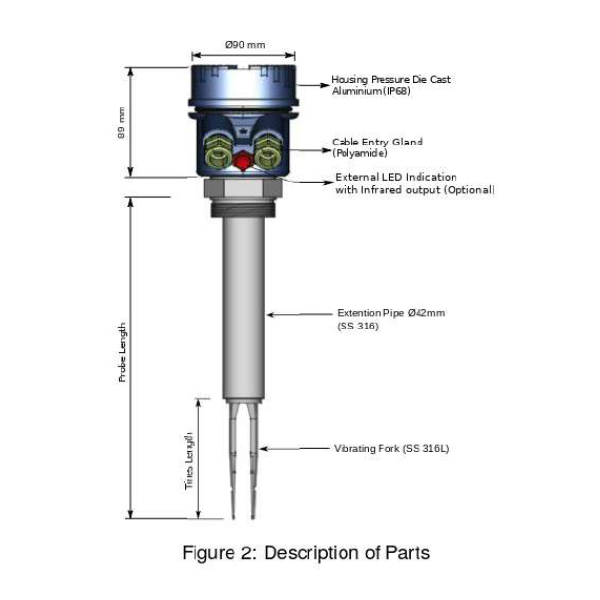
System Description
This elixir level detecting system consists of a micro controller based electronic insert with fork probe. The instrument comprises of an electronics SS 316 tuning fork housed in a cast aluminium housing provided with 2 suitable cable entries. The fork is of a special shape suitable for operating in liquids of specified range of viscosities. This is provided with either screwed mounting or flanged mounting suitable for installation on to a container or pipeline. Piezo ceramic elements are mounted inside the fork capsule and potted with epoxy compound for rendering them immune to dust, moisture and inflammable gases.
Applications
This is suitable for the following applications and industries:
- FMCG
- Paint
- Textile
- Breweries
- Cosmetics
- Chemicals
- Pesticides
- Edible Oil
- Sugar Powder
- Utility Paper
- Confectionery
- Food Industry
- Dairy Industry
- Packaging Industry
- Pharmaceutical Industry
Electrical Specifications
Please refer to Table 1 for Electrical Specifications.
Parameter |
Value |
|---|---|
| Input Power Supply and Outputs | • D: Universal Power Supply 18 – 55V DC, 90 – 265V AC, Single-point two potential free relay outputs rated at 6A • SPN: Universal Power Supply 18 – 55V DC, 90 – 265V AC – Singe-point Single relay (Rated 6A) – Open-collector PNP output, max 100mA non-inductive load • MA1 -24V DC 8/16mA 2-wire Loop powered current output • NMR: 8.2V Namur type current output (I ON = 22 to 2.5 mA, I OF F =0.8 to 1.0 mA) Namur compliance can be attained with a Namur certified isolator. |
| Power Consumption | 4W at 24V DC with 90 mA load |
| Fail-safe Settings | User selectable (Field selectable through toggle switch) • Open: Fail-safe High • Close: Fail-safe Low |
| Time Delay Settings | Cover and Uncover Delay: 0.8s / 1s to 20s, through toggle switches |
| Sensitivity Setting | Field Selectable (through toggle switches) |
| Protection | If required, additional over current and short-circuit protections can be provided with the use of an external fuse rated for 500mA. |
Table 1. Electrical Specifications
Application Specifications
Please refer to Table 2 for Application Specifications.
Parameter |
Value |
|---|---|
| Response Time | • Cover Delay 0.8 seconds • Uncover Delay 1 seconds |
| Hysteresis | 3 – 4 mm |
| Density | Above 0.7gm/cm3 |
Table 2. Application Specifications
Mechanical Specifications
Please refer to Table 3 for Mechanical Specifications.
Parameter |
Value |
|---|---|
| Active Fork Length | 44 mm and 100 mm |
| Housing | • SCUTE: Pressure die cast aluminium weatherproof (Rating IP-68) • FP2C: Cast aluminium, weatherproof & flameproof, powder coated, suitable for Gas Groups IIA, IIB & IIC as per IS-2148 |
| Mounting | • Screwed – 1”/1 1/2" BSP/NTP(M) • Flange-. As per your specifications • Material – MS (Plated), SS |
| Extension Pipe | GI (Galvanized Iron) / SS-304 / SS 316 |
| Wetted Parts | • S4: SS 304 • S6: SS 316 • SGL: SS 316L • HA: Hastelloy C • CHLR: Halar Coated • PTFE: Teflon Coated |
| Process Temperature | • A (Ambient): Below 100oC • H (High temperature): 100oC 200oC |
| Resonant Frequency | • Active Fork length of 100mm • Active Fork length of 44mm |
| Value | • Approx. 1.1KHz • Approx. 1.5 KHZ |
Switching Indication
Please refer to Table 4 for Switching Indication.
Parameter |
Value |
|---|---|
| Internal Indication | Two LEDs • Green: Normal • Red: Alarm |
| External Indication | Available only in SCUTE Enclosure |
Table 4. Switching Indication
Influences on Switching Point
1. Process Pressure – It has no significant effect on the switching point of the device as can be observed from the Figure 3.
2. Process Temperature – The influence of temperature on switching point of the device is described in Figure 4.
3. Liquid Density – The influence of liquid density on switching point of the device can be seen in the graph in Figure 5.
Installation & Handling Guide lines
This can be installed in the vessel in almost any position. Previously existing bosses welded in any direction can be used. Since the fork can be screwed into a mounting socket suitable for supplied mounting threads and the fork length is comparatively short, it can be installed directly on pipes too. For liquids with higher viscosities, top mounting or side mounting with tines slanting downwards is preferred as then the viscous liquid can drop off faster when the level goes below the set point. While installation of probe, please take care of the following points:
- The instrument shouldn’t block the material filling inlet.
- Secure the cover of housing tightly. Tighten the cable glands
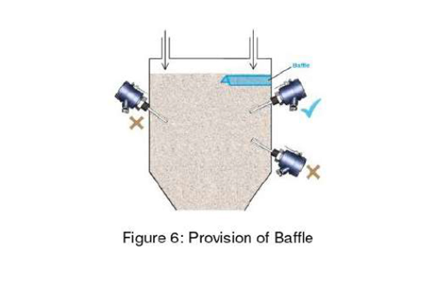
- For side-mounting, provide a baffle to prevent the material from falling on the fork. Please refer to Figure 6.
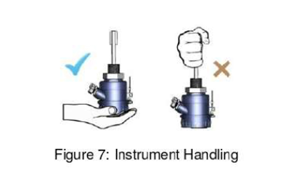
- When handling forks, do not lift them using their tines Please see Figure 7
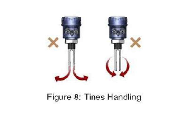
- The tines should not be bent nor should their dimensions be altered. Deforming the shape of the tines may interfere with the fork’s operating frequency. Please see Figure 8
- Make all electrical connections as instructed in the manual. Don’t power on the device before verifying connections.
- To prevent the ingress of moisture and water seepage in side mounting position, the cable entries should always point downwards.
- Waterproofness of enclosure is guaranteed only if the cover is in place glands adequately tightened. Damage due to accidental entry of water can be avoided if the instrument is installed in a rain shade.
- If the ambient temperature is high, the instrument should not be installed to receive direct sunlight. In case such a position of shade is not available, a heat shield should be fitted above the instrument especially if the operating temperature lies between 60°C and 80°C.
- While screwing the elixir instrument, the hexagonal mounting bush should be turned and not the housing.
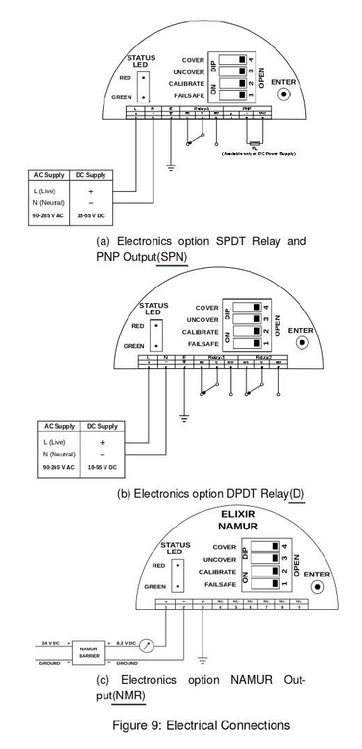
Electrical Connections
Please refer to the Figures 9a, 9b and 9c for the same.
Calibration Settings
Follow the below procedure for calibrating the instrument at notch point.
To start with calibration, set calibration switch to CLOSE position. (CLOSE is opposite of OPEN on the DIP switch.)
Make sure that Status LED is not blinking for error.
Dip the fork till the notch point.
Then press ENTER.
The Status LED will blink in RED color.
Blinking indicates that elixir is registering the switch point position
Keep ENTER key pressed for 4 to 5 blinks.
Then release the ENTER key.
On Release, the status LED should:
– Turn RED for Maximum Failsafe Selection.
– Turn Green for Minimum Failsafe Selection.
– This indicates that calibration is correct.
Now test the calibration by dipping and removing the tines from liquid.
During calibration, delays are automatically by-passed.
If calibration is correct, put the calibration switch back to the OPEN position.
Else, switch will indicate error after 2 minutes of pressing the ENTER key for the last time.
If calibration is incorrect, repeat the above stated steps once again.
Cover Delay
When the application material covers the fork tines, the changeover of the output can be delayed by a pre-determined time. This time is called COVER Delay. For a different value of Cover Delay, the number of blinks can be adjusted as per requirement.
Note:
You can set the value of COVER DELAY between 1- 25 secs.
Follow the below procedure for setting Cover Delay.
1. Ensure that all DIP switches are in OPEN position as shown in Figure 10. Make sure that STATUS LED is not blinking for Error.
2. To set the Cover Delay, set the COVER switch to CLOSE position as shown in Figure 11.
(CLOSE is the opposite of OPEN for a DIP switch.) The STATUS RED LED will glow.
3. Press ENTER and keep it pressed as shown in Figure 12. The STATUS RED LED will start blinking. Count the number of blinks. After setting the value release the ENTER key.
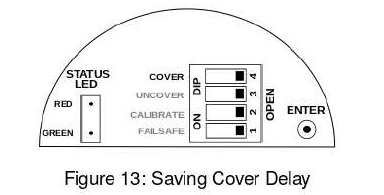
4. Delay is entered, but not saved. To save and test the Cover Delay, set the COVER switch back to OPEN position as shown in Figure 13. The STATUS LED will come back to its original position.
5. To test, dip switch into the application material until the switching point is reached.
The STATUS LED will start blinking RED if the switch point is reached. It will blink for the number of seconds for which the cover delay is set. 1 blink is equal to 1 second during switching. A maximum of 25 seconds can be set.
Uncover Delay
When the application material uncovers elixir’s fork tines, the changeover of the output can be delayed by a pre-determined time. This time is called UNCOVER Delay. For a different value of Uncover Delay, the number of blinks can be adjusted as per requirement.
Note:
You can set the value of UNCOVER DELAY between 1-25 secs.
Follow the below procedure for setting Uncover Delay.
1. Ensure that all DIP switches are in OPEN position as shown in Figure 10. Make sure that STATUS LED is not blinking for Error.
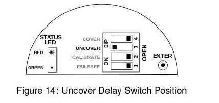
2. To set the Uncover Delay, set the UNCOVER switch to CLOSE position as shown in Figure 14. (CLOSE is the opposite of OPEN for a DIP switch.) The STATUS RED LED will glow.
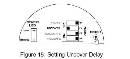
3. Press ENTER and keep it pressed as shown in Figure 15. The STATUS RED LED will start blinking. Count the number of blinks. After setting the value release the ENTER key.
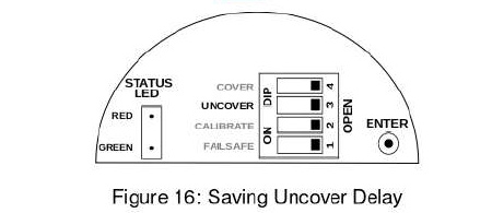
4. Uncover Delay is entered, but not saved. To save and test the Uncover Delay, set the UNCOVER switch back to OPEN position as shown in figure 16. The STATUS LED will come back to its original position.
5. To test, dip switch into the application material until the switching point is achieved.br>
6. The STATUS LED will start blinking GREEN if the switch point is achieved. It will blink for the number of seconds for which the Uncover Delay is set.
16 Failsafe Settings
In a condition of device failure, known errors and input power failure the outputs of the device resemble the ALARM condition. This is meant to prevent overflow or dry run conditions in case of failures.
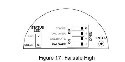
Prevent Overflow – High Level Switch Failsafe High (default) is set by moving the Failsafe switch to OPEN position.
1. When not in contact with the material, LED turns GREEN
2. When in contact with the material. LED turns RED.
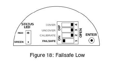
Prevent Dry run – Low Level Switch Failsage low is set by moving the Failsafe switch to Close position.
1. When in contact with the material, LED turns Green.
2. When not in contact with the material, LED turns RED.
17 Troubleshooting & Fault Indication
17.1 Output Indications
Green LED Glows When:
Fork is Uncovered and Fail-safe is High
Fork is Covered and Fail-safe is Low
Red LED Glows When:
Fork is Covered and Fail-safe is High
Fork is Uncovered and Fail-safe is Low
17.2 Error Indications
1. Temperature
Blue LED glows when temperature of electronic insert goes above 120°C.
2. Loss of Vibration
When Red LED blinks continuously and Fail-safe is High
When Green LED blinks continuously and Fail safe is Low
Troubleshooting: The following reasons may be responsible for the absence of vibrations in the fork:
The instrument is damaged.
The instrument is working but there may be solid particles in the application medium clogging the fork.
Heavy build-up of application medium can dampen the fork oscillations. In this case, the fork requires to be cleaned.
If material is very viscous, the fork vibrations will resume when the fork is uncovered. In this case, the error indication should be ignored.
3. No LED Glows
This would happen in absence of power supply to the instrument.
4. Line Break to Piezo Drive/Oscillator
In fail-safe ‘High’ mode, instrument will switch to alarm condition if the connectivity between vibrating fork and electronics is lost.
18 Maintenance
The electronics of elixir Instrument needs no maintenance. When cleaning and checking the vessel, free the tuning fork from deposits. If the material has tendency to form a hard-sticky deposit, the instrument must be checked more often. Make sure that the cable ducts and the lid are tightly sealed so that no moisture seeps into the instrument.
19 Customer Support
Thank you for going through the instructions given in this manual. To further ease the process of installation and use, we have developed special demo videos which are hosted on YouTube.
Should you require further information regarding installation, use or working of the instrument, please don’t hesitate to contact us. Kindly provide the following information at the time of contacting:
Instrument Model and Serial Number
Purchase Order Number and Date of Purchase
Description of the query
Your contact details
In an attempt to serve you better, we are open seven days a week (9:30 am to 7:30 pm). We are available at: