
- Call Us:
+66(0) 2 730 6500
- Email:
info@brasten.com
Truck Loading Arms
Bottom Loading Arms
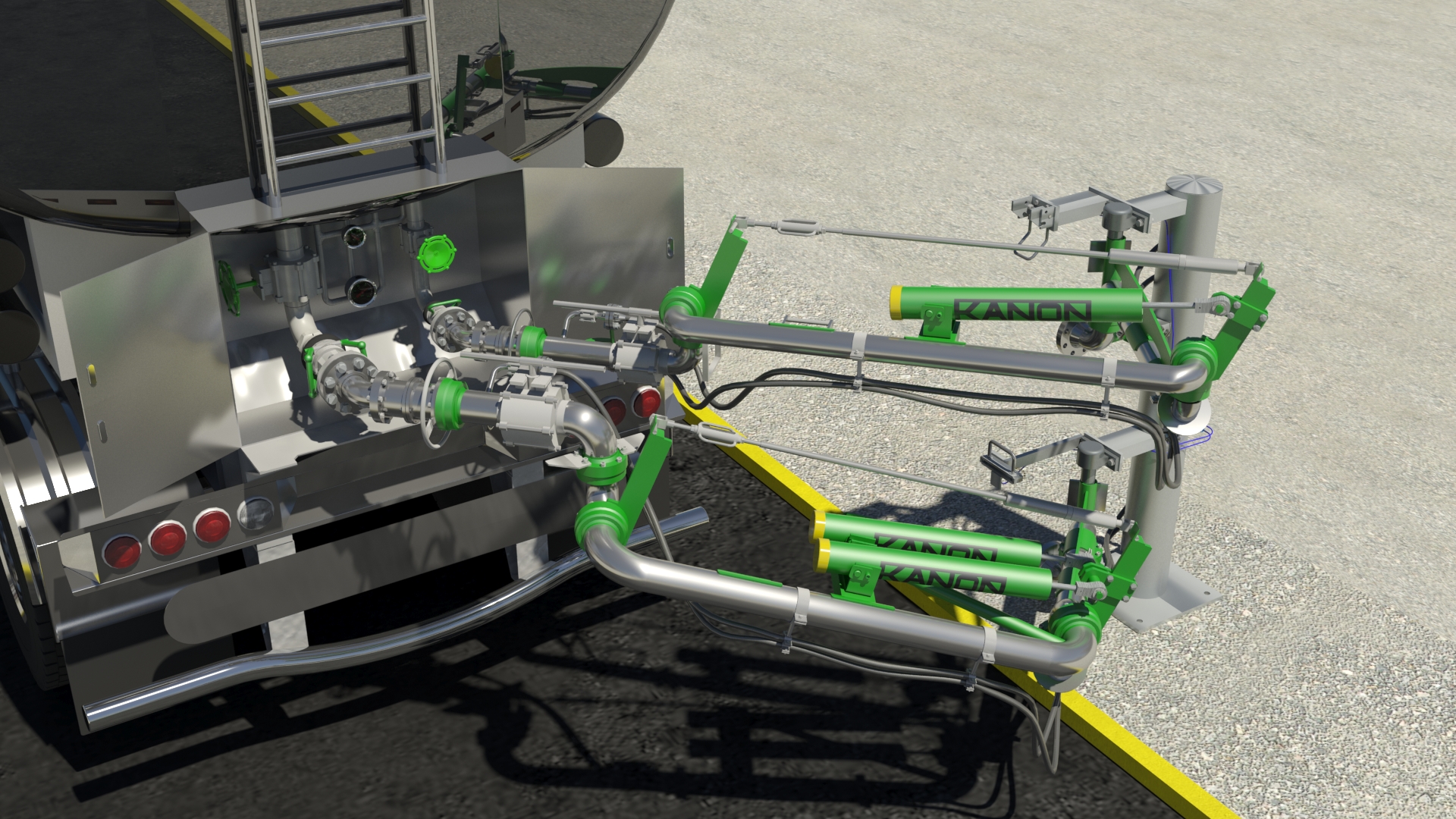
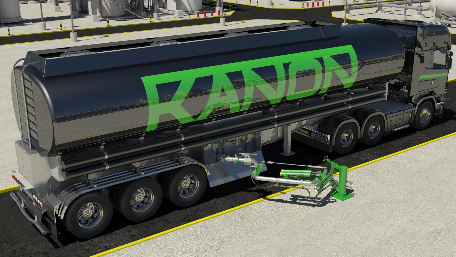
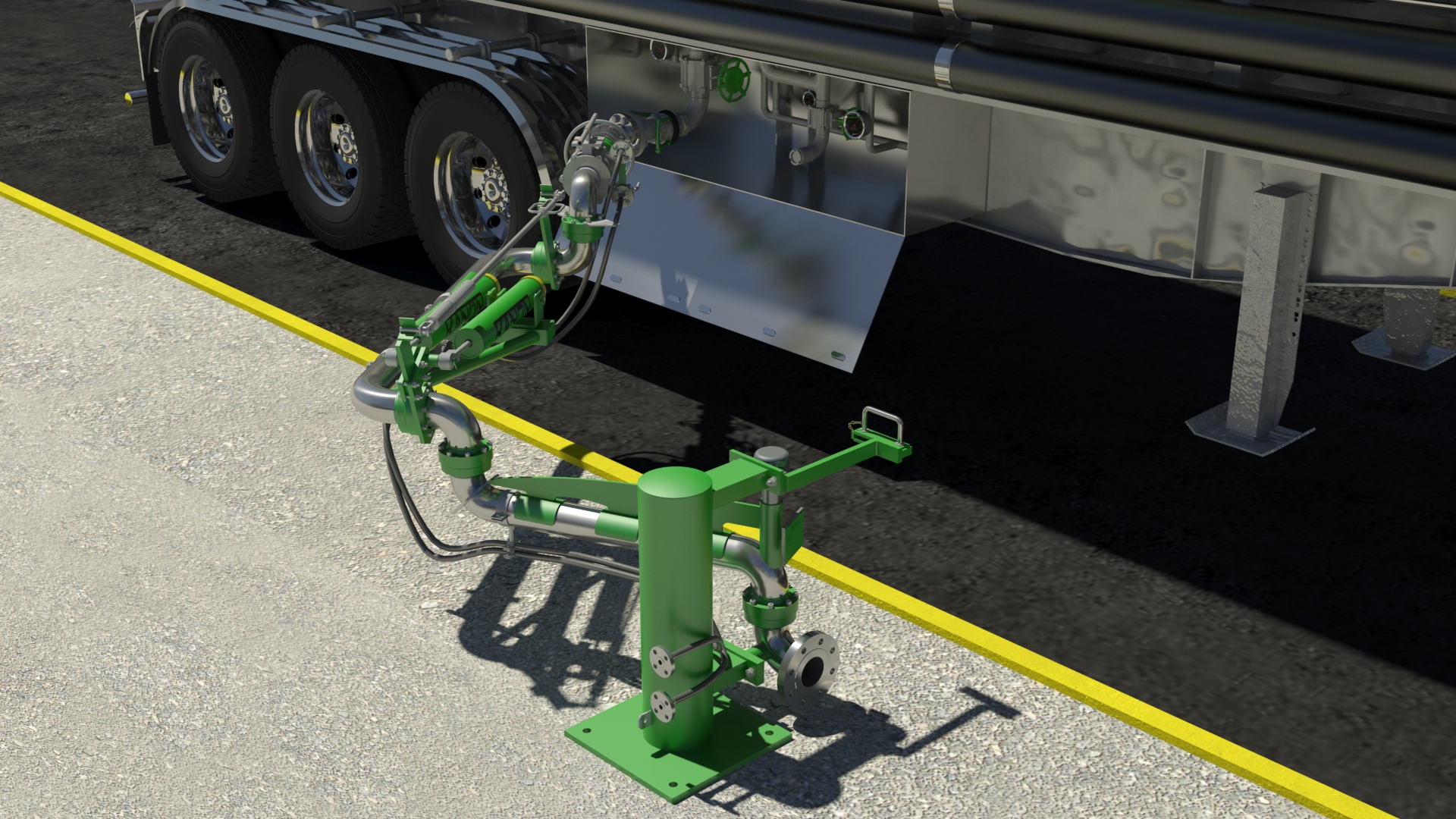
Bottom loading/unloading arms are designed to be connected on the side or on the rear of the tanker and sometimes for both.
Bottom loading arms are provided with 5x or 6x swivel joints and 1x balancing system (spring cylinder). In order to keep the connection pipe horizontal, bottom loading arms (type BLA124. BLA125, BLA144, et BLA145) are provided with a pantograph. They can equipped with a large number of accessories.
Depending on the requirements involved, the design can vary from standard solution to tailor made.
Basic characteristics
Basic characteristics
- Diameter : 2’’ (DN50), 3’’ (DN80), 4’’ (DN100) et 6’’ (DN150)
- Materials (piping) : Carbon steel, Carbon steel Low Temperature, Stainless Steel 304L, Stainless steel 316L, PTFE lined, other material on request
- Product seal : PTFE-C, PTFE virgin, FPM, NBR, UHMW-PE, other material on request
- Balancing: counterweight or spring cylinder
- Balancing : Spring cylinder
- Temperature range: -200ºC up to +300ºC
Pressure range: maximum 63 bar
Design data may include:
- Required norm : CE Machinery Directive 2006/42/EG, PED 97/23/CE, ASME B31.3, EN13480, ATEX 94/9/CE
- Type of product, viscosity, density
- Flow rate
- Unloading by gravity
- Site and existing working conditions (loading platform height, height of inlet flange of product line, roof…)
- Connection to tanker: flange, coupler…
- Detection of stored, working position
- Heating (electric, steam, hot oil) with or without insulation
- Number of loading arms working together on the same tanker
- Combination with shut-off valves, metering skid, weighbridge
Bottom Loading Arms Accessories
Accessories for bottom loading arms
- Mounting column or mounting plate
- Vapour return hose, mounted piggy back along the loading arm or rigid Vapour arm
- Heating (electric, steam, hot oil) with or without insulation
- Safety break valve in combination with connection by flange of dry-break coupler.
- Purge, drain in combination with connection by flange of dry-break coupler.
- Connection to tanker: flange, coupler…
- Main valve (butterfly, ball valve etc…) manual or pneumatic
- Detection of stored, working position
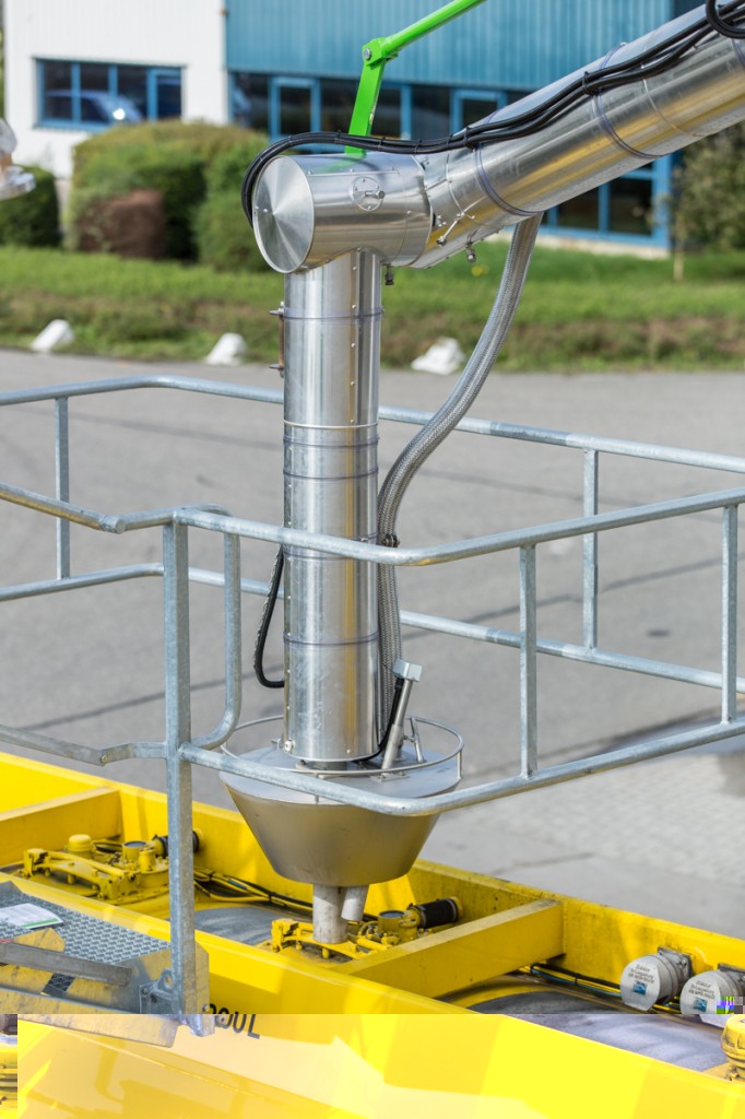
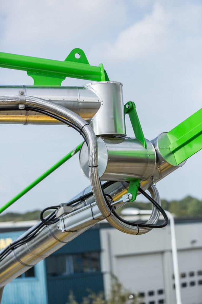
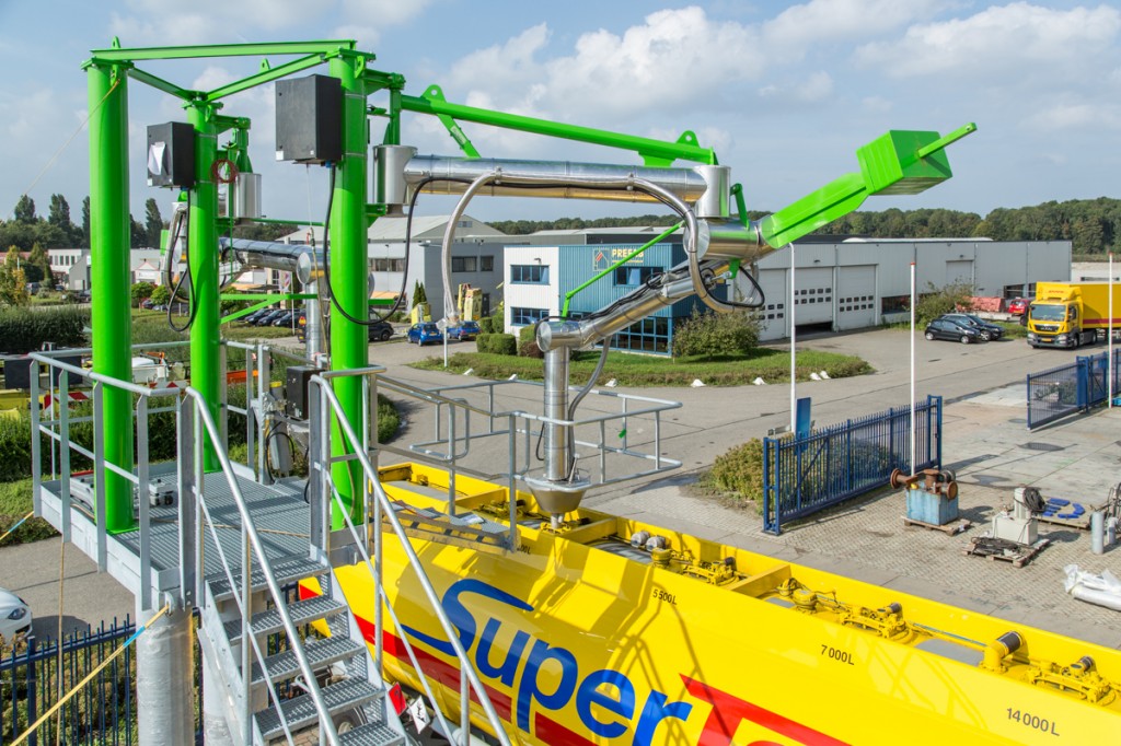
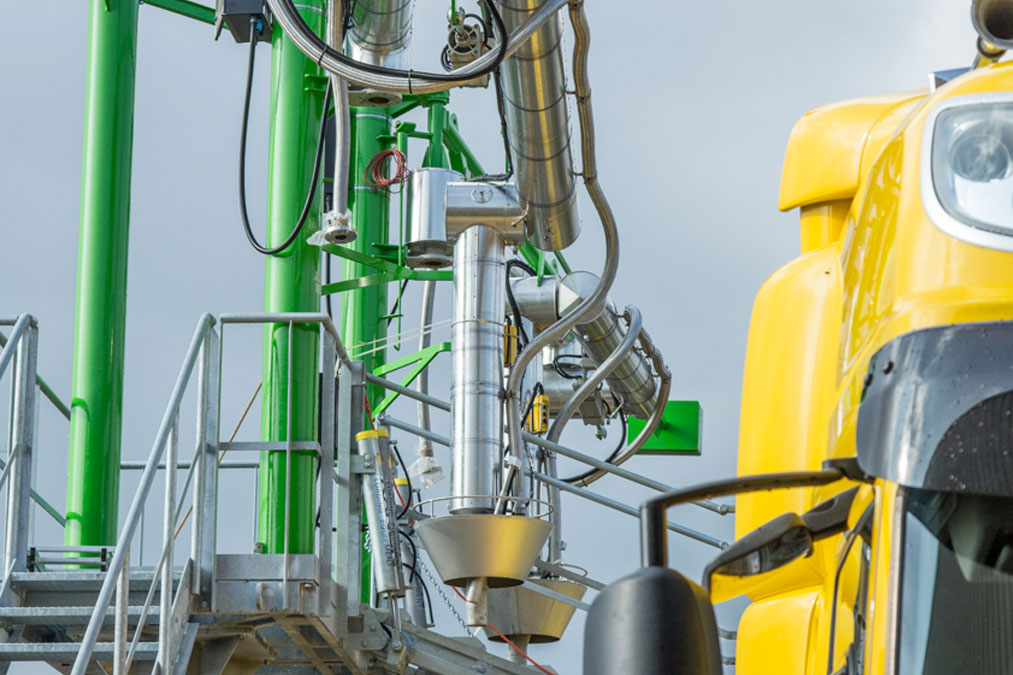
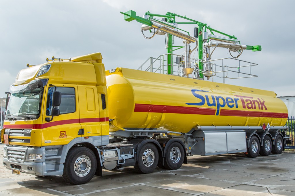
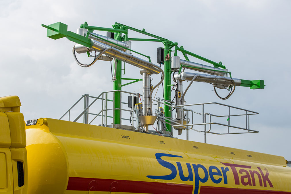
Top Loading Arms
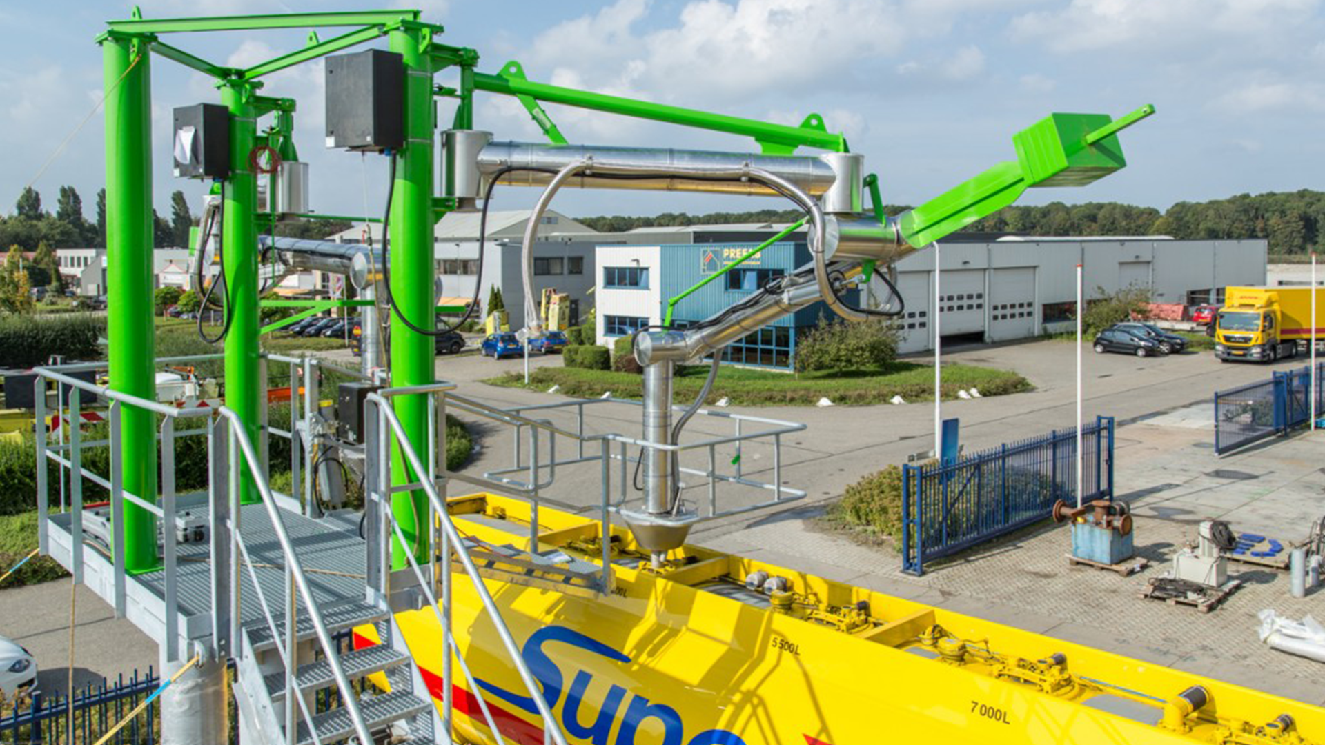
Top loading arms are designed to load (or unload) tanks from by the top. These tanks can have different dimensions and can be either truck, railcar, small or big container, ISO container, drums de 220 litres…
Top loading arms are provided with 4x swivel joints and a balance system (counterweight or multi-coil spring cylinders). They can equipped with a large number of accessories. Depending on the requirements involved, the design can vary from standard solution to tailor made.
Basic characteristics
Basic Characteristics
- Diameter : 2”(DN50), 3”(DN80), 4”(DN100) and 6”(DN150)
- Product seal : PTFE-C, PTFE virgin, FPM, NBR, UHMW-PE, other material on request
- Balancing: counterweight or spring cylinder
- Temperature range: -200ºC up to +300ºC
- Pressure range: maximum 63 bar
Design data may include:
- Required norm : CE Machinery Directive 2006/42/EG, PED 97/23/CE, ASME B31.3, EN13480, ATEX 94/9/CE
- Type of product, viscosity, density
- Flow rate
- Site and existing working conditions (loading platform height, height of inlet flange of product line, roof…)
- Connection to tanker: manhole bracket, cone, coupler…
- High level detection
- Stored position, working position detection…
- Heating (electric, steam, hot oil) with or without insulation
- Number of loading arms working together on the same tanker
- Combination with shut-off valves, metering skid, weighbridge
Top Loading Arms Accessories
Accessories for top loading arms
- Mounting column or mounting plate
- Manhole bracket, cone, coupler
- Vapour return hose, mounted piggy back along the loading arm
- Deflector on C-pipe: bevelled end 45º, plate, T-form
- Heating (electric, steam, hot oil) with or without insulation
- Telescopic pipe (manual or pneumatic)
- Stored position, working position detection…
- High level detection (tuning fork, bubbling pipe)
- Pneumatic press-unit
- Pneumatic press-unit with Up-Down movement
Vacuum breaker - Push buttons Start – Stop
- Drip bucket
- Safety break valve in combination with connection by flange of dry-break coupler.
- Purge in combination with connection by flange of dry-break coupler.
- Vertical balancer with 5th swivel joint in combination with connection by flange of dry-break coupler.
- Main valve (butterfly, ball valve etc…) manual or pneumatic
- Mechanical lock down device to keep the arm in working position