Level Transmitter
DESCRIPTION
Brasten Displacement type Level Transmitter is designed to sense Liquid level, Interface and Specific Gravity. The output of the Instrument is proportional and is designed to measure and transmit electrical signal proportional to changes in Liquid level or Specific Gravity.
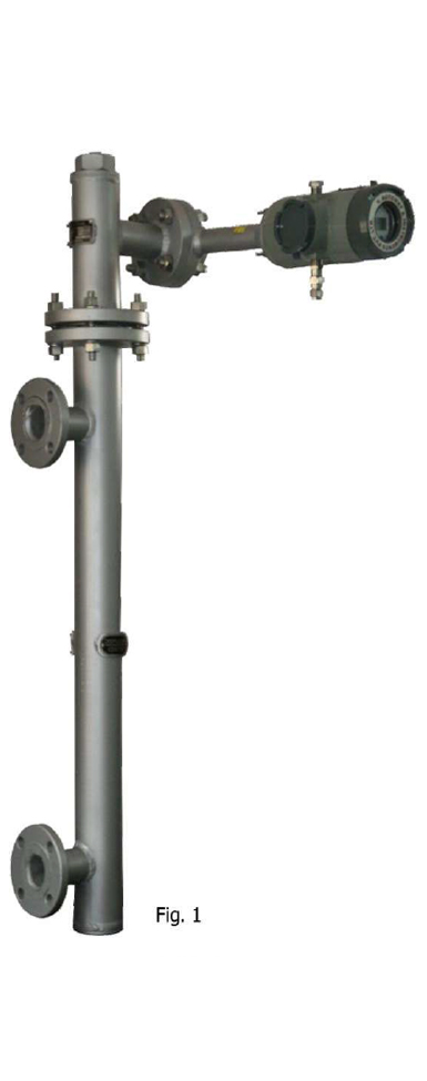
The Brasten series 401E measures changes in Liquid Level, Specific Gravity or interface Level and transmits a current output signal proportional to the change in the process parameter. The change in the process parameter causes a change in the displacer position, which is transferred to the Torque Tube (Fig.1) producing a rotary motion. This rotary motion is transferred through bellow to lever assembly that is supported by flexure strips. Magnets attached to the lever assembly move past a Hall effect position sensor that converts the magnetic field signal to an electrical 4-20mA signal.
The Transmitter has been provided with magnet setting Pin which can be used to adjust setting of magnet in relation to hall effect sensor. Magnet setting Pin can also be used to check for fault finding between Mechanical system & electronic system. The magnet sensing Pin allows to find out problem without removing the transmitter or field Wining cover or the signal Conditioner Cover. The above adjustment does not require raising or lowering of the level. This facility is only available in Brasten displacement type level transmitter

INTRODUCTION
Brasten Displacement level transmitter consist of certified electronic. This assembly along with hall effect sensor makes complete level transmitter. SMART displacement level transmitters are microprocessor-based instruments that combine the analog signal advantages (4-20mA) together with the flexibility of digital communication using HART® protocol/Foundation Field Bus (FF). Displacement level Transmitter can be configured by using universal Hand-Held HART communicator (HHC) or by Computer (PC) with dedicated software. The facility of Brasten design is easy calibration by any of the three different methods i.e. HHC as well as by PC with Dedicated software and by push button.
PRINCIPLE OF OPERATION
A Level density, or interface level change in the measured fluid causes a change in displacer position. This change is transferred to the Torque Tube assembly. As the measured fluid changes, the Torque Tube assembly rotates upto 3.7 degrees changing the transmitter output between 4 and 20mA.
The rotary motion is transferred to transmitter lever assembly (via a bellow) supported by flexure strips. The rotary motion moves a magnet attached to the lever assembly, changing the magnetic field that is sensed by Hall effect position sensor. The sensor then converts the magnetic field signal to an electronic signal. The electronic signal is ambient, temperature compensated and amplified by the differential amplifier the low pass filter dampens the effects of process turbulence and prevents saturation of the dc amplifier and the current driver.
The current driver circuit develops 4 to 20mA current output signal proportional to the dc amplifier voltage output. The voltage regulator provides the regulated voltage needed by the transmitter. Circuits within the transmitter provides Reverse polarity protection, Transient power surge protection, and Electromagnetic interference (EMI) protection.
Available Configuration
| 401 E Digital Level Controller | Mounts on caged and cage less i.e. top mounted |
| Function | Transmitter |
| Communication protocol: | HART/FF |
Input Signal
Level, Interface or density: Rotary motion of torque tube shaft proportional to changes in liquid level, interface level or density that changes the buoyancy of displacer.
Output signal
| Analog: | 4 to 20mA DC (Direct action – Increasing level, Interface or density increase output) (Reverse action- Increasing level, Interface or density decrease output) |
| High Saturation | 20.5 mA |
| Low Saturation: | 3.8 mA |
Operating Influence
Power supply Effect : Output changes <+/-0.2% of full scale when supply varies between minimum and maximum voltage specifications. Transient Voltage protection : The loop terminals are protected by a transient voltage suppressor. Ambient Temperature : The combined temperature effect on zero and span is less than 0.03% of full scale per degree Kelvin over the operating range -40 to 80 deg. C (- 40 to 176 deg. F) Process Temperature : The torque rate is affected by the process temperature. The process density may also be affected by process temperature. Process density : The sensitivity to error in knowledge of process density is proportional to the differential density of the calibration. If the differential specific gravity is 0.2. an error of 0.02 specific gravity units in knowledge of process fluid density represents 10% of span. [/kc_column_text][/kc_accordion_tab][kc_accordion_tab title="Electromagnetic Compatibility" _id="312381"][kc_column_text _id="173871" css_custom="{`kc-css`:{`any`:{`typography`:{`color|,p`:`#000000`,`font-family|,p`:`roboto`,`text-align|,p`:`justify`},`box`:{`padding|`:`10px 10px 10px 10px`,`margin|p`:`10px 10px 10px 10px`}}}}"] Radiated Electromagnetic test as per IEC 61000-4-3 Radiated Emission limit test as per IEC 61000-6-4 [/kc_column_text][/kc_accordion_tab][kc_accordion_tab title="Supply requirement" _id="548637"][kc_column_text _id="187659" css_custom="{`kc-css`:{`any`:{`typography`:{`color|,p`:`#000000`,`font-family|,p`:`roboto`,`text-align|,p`:`justify`},`box`:{`padding|`:`10px 10px 10px 10px`,`margin|p`:`10px 10px 10px 10px`}}}}"] 12 to 30 volts DC; instruments has reverse polarity protection. A minimum compliance voltage of 17.75 is required to guarantee HART Communication. [/kc_column_text][/kc_accordion_tab][kc_accordion_tab title="LCD meter Indication" _id="98935"][kc_column_text _id="864411" css_custom="{`kc-css`:{`any`:{`typography`:{`color|,p`:`#000000`,`font-family|,p`:`roboto`,`text-align|,p`:`justify`},`box`:{`padding|`:`10px 10px 10px 10px`,`margin|p`:`10px 10px 10px 10px`}}}}"] LCD meter indicates analog output on a percentage scale. The meter also can be configured to display: mA (milliampere), %(Percentage), mm(millimetre) [/kc_column_text][/kc_accordion_tab][kc_accordion_tab title="Minimum Differential Specific Gravity" _id="330795"][kc_column_text _id="83238" css_custom="{`kc-css`:{`any`:{`typography`:{`color|,p`:`#000000`,`font-family|,p`:`roboto`,`text-align|,p`:`justify`},`box`:{`padding|`:`10px 10px 10px 10px`,`margin|p`:`10px 10px 10px 10px`}}}}"] With a nominal 3.7-degree torque tube shaft rotation for a 0-100 percent change in liquid level (Specific gravity=1), the digital level controller can be adjusted to provide full output for an input range of 20% of nominal input span this equates to minimum differential specific gravity of 0.05 with standard volume displacer. [/kc_column_text][/kc_accordion_tab][kc_accordion_tab title="Construction material" _id="414140"][kc_column_text _id="748846" css_custom="{`kc-css`:{`any`:{`typography`:{`color|,p`:`#000000`,`font-family|,p`:`roboto`,`text-align|,p`:`justify`},`box`:{`padding|`:`10px 10px 10px 10px`,`margin|p`:`10px 10px 10px 10px`}}}}"] Case and cover (Electronic Enclosure): Die cast Aluminium (for other please contact factory) [/kc_column_text][/kc_accordion_tab][kc_accordion_tab title="Electrical Connection" _id="112335"][kc_column_text _id="179126" css_custom="{`kc-css`:{`any`:{`typography`:{`color|,p`:`#000000`,`font-family|,p`:`roboto`,`text-align|,p`:`justify`},`box`:{`padding|`:`10px 10px 10px 10px`,`margin|p`:`10px 10px 10px 10px`}}}}"] Two 1/2" NPT internal conduit connections, one on bottom and one on Top of terminal box. Note: At full design span, reference conditions
| Sr. No. | Performance Criteria | 401E Digital level Transmitter |
|---|---|---|
| 1 | Independent Linearity | +/- 0.25% of output span |
| 2 | Hysteresis | <0.2% of output span |
| 3 | Repeatability | +/-0.25% of full-scale output |
| 4 | Dead Band | < 0.05% of input span |

SPECIFICATIONS
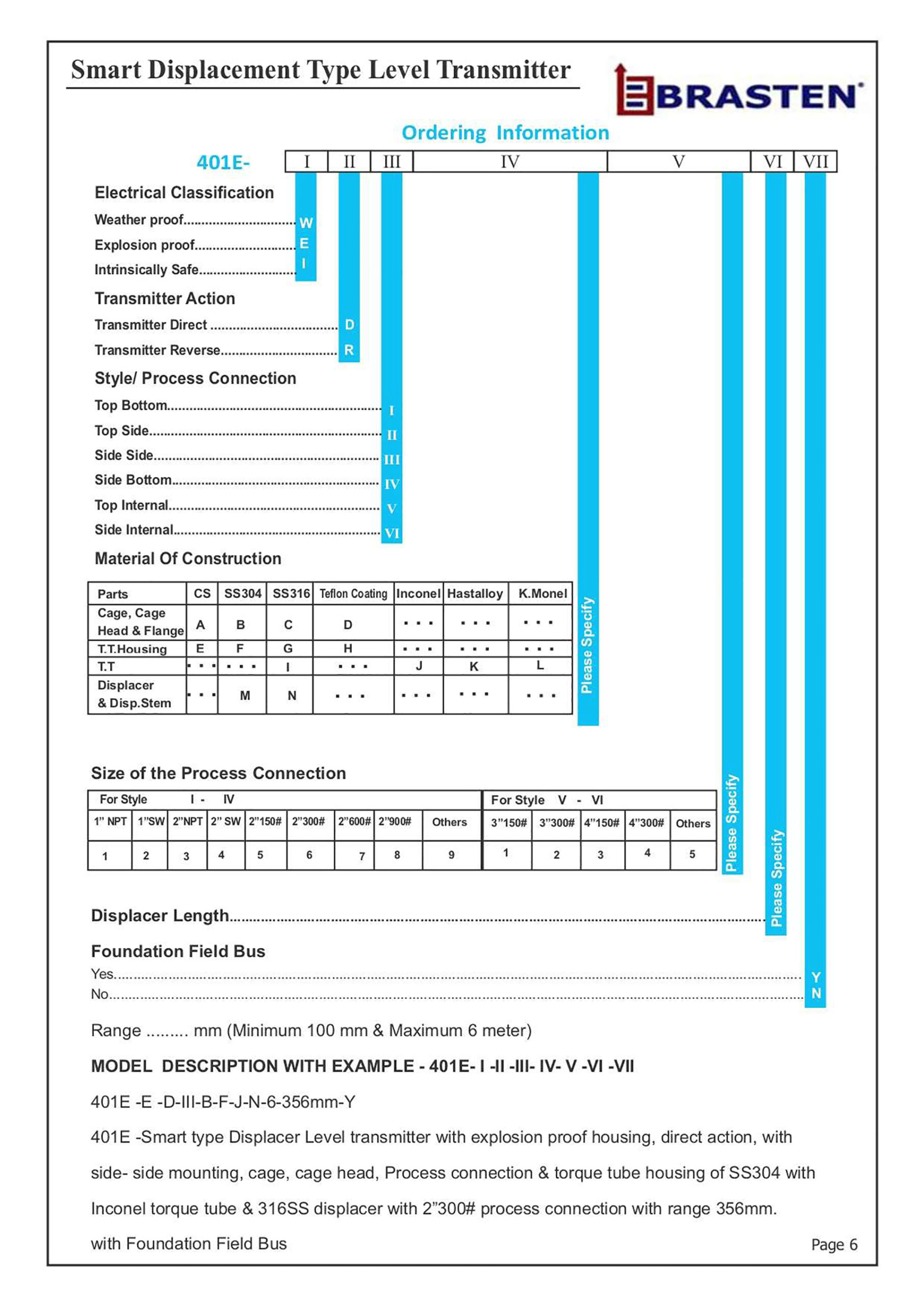
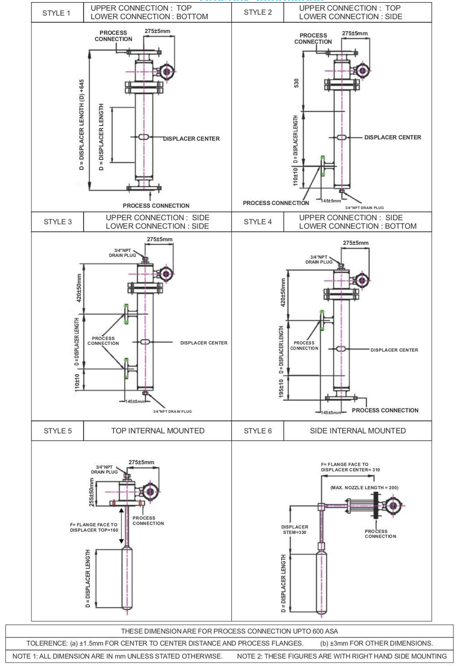
Displacer lengthMinimum 100 mm & Maximum 6 metersInput SignalLiquid level or liquid to Interface Level: From 0 to 100% of Displacer lengthSpecific Gravity Range0.4 to 1.4 (with Standard Displacer) & 0.2 (For interface)Output SignalTwo Wire 4-20mA dc.Output ActionDirect- increasing Level increases output: or Reverse- increasing Level decreases outputDisplayLCD Display Meter 3 1/2 DigitMeasuring unitmA, %(Percentage), mmReference accuracy at (specific gravity 1.0)+/- 0.5% of full scale (better on request)Damping0-32 secCalibration facilityBy three methods i.e. Hand-Held Communicator (HHC), push button & PCPower Supplya) 35 V dc for explosion proof b)30 V dc For intrinsically safePower Supply effectNegligible between 13 and 35 VdcLoad Resistance600 ohms at 24 V dcSpan Adjustability+ 20% of Displacer length for LevelZero AdjustabilityContinuously AdjustableDiagnostic of Mechanical & ElectronicProvidedCage StyleCages can be famished in a variety of end connection style to facilitate mounting on vessels. (Pls Refer Page 7)Amb.Temp-40 to 70°CElect. Connection1/2" NPT(F)x2Elect. Connection1/2" NPT(F)x2HousingDie cast AluminiumElect. Classification1. Weather proof IP 66
2. Explosion proof for group IIA, IIB & IIC cum Weather proof
3. Intrinsically safe
4. CCOE, DGMS & Others on request.MOCExternal: Carbon Steel, 30455 , 3165S, 304L & 316L & other
Internal: 316SS. & otherTorque Tube316SS,316L, Inconnel, K Monel & Hastelloy,Process ConnectionsS.W or Flanged.Max. Working Pressure0-100kg/cm2Process Medium Temp(-)50°C to (+)400°C (Cooling fins are provided for Process Temperatures above 150°C)Static Pressure150% of working Pressure

Feature
Simplified setup and calibration- For quick analog transmitter replacement (4-20mA output only, the instrument may be configured with default sensor data, zero level offset, differential process SG, and zero/span procedure only. For full compensation and diagnostic capabilities, complete sensor data entry and calibration is recommended.
Responsive to small process change- Accurate, high-gain analog to digital conversion enables measurement of small changes the process variable. This allow the 401E digital level controller to be used in difficult liquid level, interface or density applications.
Compensation – The instruments measurement algorithm corrects for the small motion of the displacer as buoyancy changes, allowing it to calculate the true cage or vessel level. This provides additional accuracy on the shorter displacer.
Rugged construction – Mechanical safeguards designed into the digital level controller help it to withstand physical abuse often incurred during installation or in transport, without compromising performance. The encapsulated printed wiring board resist the effect of vibration, temperature and corrosive atmospheres. The lever assembly is pinned at the neutral position when the coupling access door is open, providing shipping stabilization for a separate transmitter purchase. Locking set screws are provided for covers and the access door handle.
Easy Maintenance – Field wiring connections are in a compartment separated from the electronics. This protects the electronics from any moisture brought into the housing by the field wiring. This also eases installation and maintenance. The digital level controller does not have to be removed to facilitate troubleshooting or service. Modular construction allows servicing in the field. However, if it is necessary to remove the digital level controller for in shop maintenance and calibration, field wiring does not need to be disconnected.
Alarm Jumper – The 401E digital level controller induced self-diagnostic that detect an error (e.g. electronic failure) that would render the process variable measurement inaccurate. The instrument can also be configured to indicate a process variable high or low alarm. When a process variable alarm or an error is detected the analog output signal is driven either above or below the normal 4 to 20 mA range, depending on the user selectable position of the alarm jumper. The units from the factory with jumper in the high position.
FOUNDATION FIELD BUS FEATURES
- Transmitters on the main field bus segment is able to communicate at a speed of 31.25 Kbps as a minimum.
- Transmitter will support peer to peer communication.
- Transmitters complying interoperability test clearance ITK6.1.1 for foundation field bus.
- Transmitters are capable to operate between 9-32 VDC maximum.
- Transmitters have capability to perform continuously their own self diagnostics to check their own health status.
- Transmitters have EDDL (Electronic Device Description Language) enabled as per IEC61804 latest Version.
- Transmitters are able to update output at the rate of 250msec.
- Transmitters have capability to provide input & function blocks such as signal linearization, input selector, arithmetic function, integrator and PID as a minimum.
- Function block execution time 25msec for analog input, 31.25 msec for PID.
- Transmitters are able to provide diagnostics as real time instruments status.
- Transmitters have capability to become device link master.


SPECIFICATIONS OF SMART TRANSMITTER (HART Protocol)
| Transmitter Tube | Stainless Steel |
| Max. Transmitter Length | 12 meters |
| Terminal Box | Aluminium |
| Resolution | 20mm standard |
| Supply input | 24V dc |
| Output | 4-20mA for load upto 600 ohms |
| Transmitter Housing | General purpose/ Weather Proof/ Explosion Proof |
Part List Key Description Part Name - Part Code
| O-Ring, Nitrile | E4003 |
| Printed Wiring Board Assembly with Display unit (LCD) | E4007 |
| Funnel plate m/c screw | E4011 |
| Stud, Stainless Steel (4req’d) | E4013 |
| Hex Nut Stainless Steel | E4014 |
| Funnel Plate, Stainless Steel | E4015 |
| Lever Assembly, Aluminium | E4016 |
| Cap Screw, SS (2req’d) for lever assy, mounting | E4017 |
| Housing Aluminium | E4020 |
| Housing Cover, Aluminium | E4021 |
| Vent Plug | E4022 |
| Sensor Assembly, Stainless Steel | E4023 |
| O-Ring, Nitrile | E4024 |
| Sensor Screw | E4025 |
| Adapter Ring | E4030 |
| Torque Tube | E4033 |
| Displacer | E4034 |
| Displacer Arm | E4035 |
| U Bearing | E4036 |
| Positioning Plate | E4037 |
| Cotter Pins | E4039 |
| Displacer Rod | E4040 |
| Top end Piece | E4041 |
| Electronic unit | E4042 |
| Torque tube Housing | E4043 |
Cautions for handling the product
In order to ensure maximum performance from the product’s functions, please handle it properly while paying attention to the following precautions. Please make sure that you read the instruction manual of this product before use.
Cautions for handling the product
In order to ensure maximum performance from the product’s functions, please handle it properly while paying attention to the following precautions. Please make sure that you read the instruction manual of this product before use.
Warning
- When Installing, make sure that the gasket between process connections (Flange connections) does not protrude; otherwise fluid leakage or output error may occur.
- Do not operate the instrument beyond the specified pressure, temperature or conditions could result in damage to the instrument or fluid leakage which may lead to a serious accident.
- Wiring installation in an explosion proof area must be done in accordance with the procedure stated in the explosion guideline. For an explosion proof model with explosion proof cable gland adaptor, make sure that V.Automat made certified explosion proof cable gland adaptor is used. The cable for wiring should have a 60 deg C withstand temperature or higher
- Do not perform wiring with wet hands or while the power supply is on. This may result in electric shock.
Caution
- Do not use this instrument as a step or scaffold after installation. The instruments may be damage and this may result in injury
- Do not hit indicator’s glass window with any tool or hard object. Broken glass may cause the injury
- Make sure that installation has been performed properly. If not, it may result in output error or violation of industry regulations
- This instrument is heavy. Be careful on scaffold and wear safety shoes.
- Make sure that wiring is done property and checked thoroughly. Incorrect wiring may damage the instrument.
- Make sure that the power supply conforms to specifications and is used properly. An incorrect power supply will damage the instrument
