Liquid Level Switches
Top Mounted (Float Operated) Level Switch Series 40H-3
Description
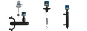
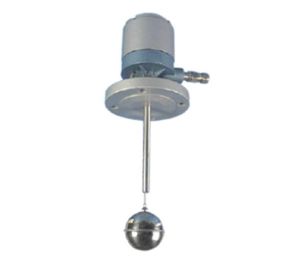
The 40H-3 level switch is designed for internal mounting through the top of the process vessel. The main advantage of these level switches is lower cost. Mounting connections are offered in as per table on page no. 3 and in a variety of flange sizes and pressure ratings.
Principle of Operation
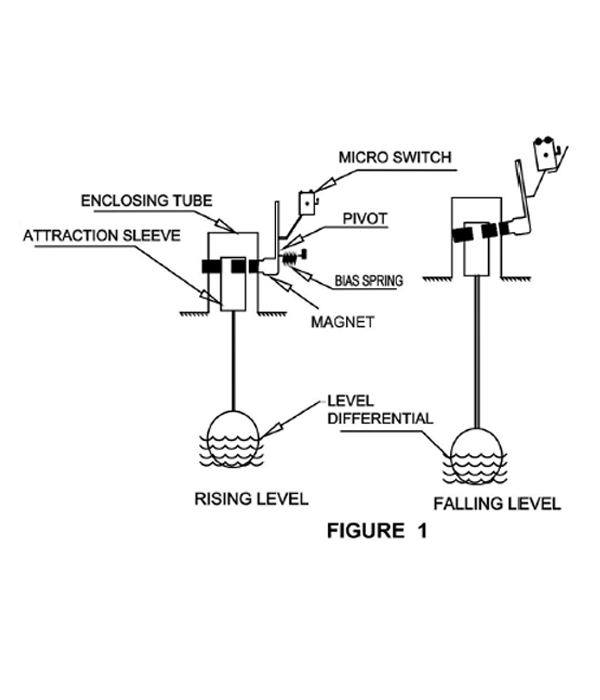
a) For Single Switch Mechanism (Series 311) (Refer Fig. 1)
The operating principle provides for magnetic switch action resulting from a change in liquid level, which moves a magnetic attraction Sleeve into the field of an externally located magnet. The illustrations given indicate the operating principle using a Float or Displacer to provide the operating motion. A falling level causes a downward movement of a magnetic Attraction Sleeve moving it below the magnetic field generated by the externally mounted alnico magnet. The bias spring then causes the magnet to pull away from Enclosing tube in turn actuating the Switch. The reverse function takes place on rising level with the Attraction Sleeve being moved into the field causing the magnet to pull in towards the Enclosing tube in turn actuating the Switch.
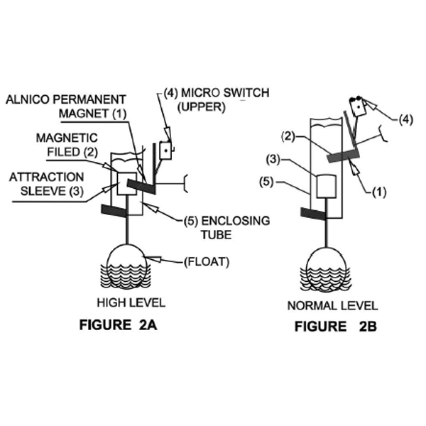
b) For Double Switch Mechanism (Series 321) (Refer Fig.2)
The Stainless-Steel Magnetic Attraction Sleeve (3) actuated by the float/Displacer, is outside the field (2) of the Alnico permanent magnet (1) the switch is in the Released position & an electrical circuit is open for (L-C) connection of Micro Switch (4). The switch is held in the “Released" position by gravity and the tension of spring which provides the snap action when the spring operates. Refer figure 2A
When the Float/Displacer causes the Attraction Sleeve to enter the field of permanent magnet associated with a given switch, the magnet swings into contact with the non-magnetic Enclosing Tube (5) & the switch is then “Actuated" (Refer figure 2B). In the actuated position of the switch there is a closed electrical circuit, between L-C of Micro Switch.
Note 1
Switch mechanism is interchangeable and may be fitted with any Level Switch provided the Switching gap does not exceed the maximum of 115 mm.
Each switch unit has a nominal differential of maximum 30mm. If a differential greater than 30mm is required for the pump control, two switch unit must be used with a holding circuit arranged for the starter control circuit. With the switches set at the minimum operation the combined differential will be between 28mm to 35mm. Wider differential may be obtained by increasing the separation between the switches Contact L-C is normally open contact and H-C is normally closed contact and these are marked on micro switch. The L-C circuit closes on a rise of water level, the HC circuit closes on a fall of water level. Each switch unit has a normal differential of maximum 30mm of liquid at SG 1.00
Specifications (for 40H-3 Model)
| Service | Condensation oil & Viscous liquids |
| Specific Gravity | Refer Table 2 on Page 3 |
| Pressure | Refer Table 2 on Page 3 |
| Temperature | 150°C without cooling fins 350°C with cooling fins. |
| Differential | a) Maximum 30mm for 1 switch assembly model (Series 311) b) 130 mm maximum with individual differential of switch as maximum 30mm for low set point & 45mm for high set point 2 switch assembly model. (Series 321) |
| Attraction Sleeve | 410 Series Stainless Steel. |
| Enclosing Tube | 304 Stainless Steel |
| Float Rod & Rod Guide Tube | 304/316 Stainless Steel |
| Electrical Connection | 1/2" & 3/4" NPT (Single cable entry standard, others optional) |
| Housing Material | Aluminium Alloy Base & Cover SS304/316 |
Series Description (Common for all 40H Series Models)
| Series 40 H | Level switch in Explosion proof & Weather proof Enclosure certified by CIMFR for groups IIA & IIB. |
| Series 40HWP | Level switch in Weather Proof IP66 Enclosure certified by CIMFR. |
Model Number Description
| 311 | Level Switch with 1 Switch Assembly and 1 Float |
| 321 | Level Switch with 2 Switch Assembly and 1 Float |
Material of Construction
Description |
Specify |
|---|---|
| C.S Plate Flange, IS 226 | 2 |
| C.S Forged Flange, ASTM-A-105 | 3 |
| Carbon Steel (for Threaded Connector) | 4 |
| 304 SS Flange / Threaded Connector | 5 |
| 316 SS Flange / Threaded Connector | 6 |
| PP Flange | 7 |
| Non-Standard Flange Material | 8 |
Tank Connection and Float
Tank Connection FloatFloat, Float Rod |
||
|---|---|---|
| Process Connection | SS 316 | PP/PVC Teflon Coated |
| 3"150 ASA | GSA | GPA |
| 3"300 ASA | GSB | GPB |
| 3"600 ASA | GSC | GPC |
| 4"150 ASA | HSA | HPS |
| 4 300 ASA | HSB | HPB |
| 4"600 ASA | HSC | HPC |
| Any Other (Pls Spy.) | NSE | HPE |
Note: For Corrosive application Float along with Float Rod and Rod Guide Pipe can be given in Teflon coated only, as solid Teflon float would increase the weight of the float assembly and cause a problem in floating. Teflon is recommended for Atmospheric pressure only.
Maximum Insertion Depth to Actuating Level w.r.t. Specific Gravity
| Liquid Specific Gravity | 1.0 | 0.9 | 0.8 | 0.7 | 0.6 |
| Float Diameter | Ø70×135 | Ø70×135 | Ø70×135 | Ø70×115 | Ø70×115 |
| Maximum Pressure Kg/cm2g | 30 | 30 | 30 | 10 | 10 |
| Range in mm | 1000 | 800 | 500 | 800 | 500 |
| Float Diameter | Ø90 | – | – | – | – |
| Maximum Pressure Kg/cm2g | 50 | – | – | – | – |
| Range in mm | 800 | – | – | – | – |
| Range in mm | 800 | – | – | – | – |
| Float Diameter | Ø90×135 | Ø90×135 | Ø90×135 | Ø90×135 | Ø90×135 |
| Maximum Pressure Kg/cm2g | 30 | 30 | 30 | 30 | 30 |
| Range in mm | 2000 | 1500 | 1200 | 800 | 500 |
The insertion depth is applicable at Ambient temperature.
| 1 | 2 | 3 | 4 | 7 |
|---|---|---|---|---|
| Page 2 | Page 3 | Page 3 | Page 3 | Page 6 |
40HWP/311/2/GSA/SSW
Defines a level switch in weather proof enclosure with float + 1 switch assembly. The flange is of carbon steel of 3" 150 ASA and float of 316 SS. Switch is SPDT of 5A 230 V AC rating.
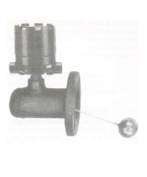
Side Mounted (Magnetic) Float Operated Level Switch (Model 40H-2)
Top Mounted (Float Operated) Level Switch Series 40H-3
Introduction
This series is designed for integral mounting through the side of the process vessel. The design provides for greater differential as compared to other float operated switches and as a result is better suited for turbulent applications.
Principle of Operation
The basic operating principle provides for magnetic switch action resulting form a change in liquid level, which moves a magnetic attraction sleeve in to the field of an externally located magnet. This principle eliminates problems associated with flexing diaphragm seals, bellows seals as well as ‘coating’ problems encountered by prove type devices. Side mounting units employ permanent magnetic force as the only link between the float and the switching element. As the pivoted float follows liquid level change, it moves attraction sleeve into or out of the field of a switch actuating magnet causing switch operation. An enclosing (non-magnetic) tube effectively isolates the switch form the controlled liquid.
Technical Specifications
| Service | Condensate, Oil & Viscous liquid |
| Differential | 25t5mm for float steam of 254mm (Float Steam length is distance between the flange face to float end) |
| Working Pressure & Temperature | 100kg/cmº @ 350°/C |
| Float Size | a) 62mm Ø x152mm long b) 90mm Ø c) 90mm Ø x135mm long |
Model Number Description 40H-2
| 1 | 4 | 7 |
|---|---|---|
| Page 2 | Page 3 | Page 6 |
40HEP/GSB/SDE: Defines a level switch Model 40H-2 in Explosion Proof Housing having 3" 300ASA Process Connection of Carbon Steel & with DPDT Switch Assembly.
Top Mounted (Displacer Operated) Level Switch Series 40H-4
The 40 H-4 Level Switch is designed for internal Mounting through the top of the Process Vessel and is also furnished with Chambers for External Mounting from the Process Vessel. The use of displacers as the sensing medium allows for wide switching differential, field adjustable switching points and use on high pressure applications. Mounting connections without chambers are offered in 3" NPT screwed & 4 150 ASA Flanged as standard. For Level Switches with Chamber, process connections are offered in Threaded, Socket weld & flanged of sizes 1". 1½ & 2" ASA.
These Level Switches are offered with either Narrow or Wide Differential. Displacers are available in 316 Stainless Steel, Teflon or Polypropylene with a 2 Meter suspension cable as standard. Special cable lengths upto 40 meters are available for internal Mounted switches only.
Principle of Operation
Displacer operated Level Switch offer control features not found in float operated controls. The basic sensing means utilizes displacer heavier than the liquid which is suspended from a spring. When the liquid contacts the displacer, a buoyancy force is produced, which causes the effective weight of the displacer to change, in turn causing the spring to seek a new balance position which moves the attraction sleeve into the field of the magnet. This principle provides for wide switching differential and allows the desired level switching point to be adjusted by moving the displacers up or down the suspension cable. Further advantage allows for adoption to high pressure applications since displacers have substantial heavier wall thickness than floats and in many cases are made out of solid materials.

Model Number Description (Series 40H-4)
| 411 | Narrow differential (fixed) type using One Switch Assembly and One Displacer. (Min. Operating point of 375 mm. (Refer Fig. 3) |
| 412 | Wide Differential (Adjustable) type using One Switch Assembly and Two Displacers. (With Minimum upper & lower operating points of 475 mm & 725mm respectively. (Refer Fig. 4) |
| 422 | Narrow Differential (Fixed) type using Two Switch Assemblies and Two Displacers. Each switch is actuated at different level and calibrated with Narrow Differential Band (with minimum upper and lower operating point of 475 mm & 775 mm respectively. (Refer Fig.5) |
| 4114 | Narrow Differential (Fixed) type using One switch assembly and One Displacer (Min operating point of 100 mm. (Refer Fig. 6) |
| 4124 | Wide Differential (Adjustable) type using One Switch Assembly and Two Displacers (With minimum upper & lower operating points of 100mm & 425mm respectively. (Refer Fig. 6) |
| 4224 | Narrow Differential (Fixed) type using Two Switch Assemblies and Two Displacers. Each switch is actuated at different level and calibrated with Narrow Differential Band (With minimum upper & lower operating point of 100 mm and 400 mm respectively. (Refer Fig. 6) |
| 4334 | Narrow Differential (Fixed) type using Three switch assembly & Three Displacer minimum operation set point form top 100mm & 400x 700mm |
Technical Specifications
| S.G | 0.6 (Minimum) |
| Differential | Maximum 70mm at S.G. 1 for models 411, 422, 4114 & 4224. Differential for Model 412 & 4124 depends upon distance between the displacers. |
| Accuracy | ±3% |
| Repeatability | ±1% |
A) Without External Chamber
| Pressure | 50 kg/cm2 (Maximum) |
| Temperature | a) S.S. & Teflon Displacers 150°C b) Polypropelene Displacers 70°C |
B) With External Chamber
| Pressure | 100 kg/cm2 (Maximum) |
| Temperature | 150°C |
Model Number Description (Without External Chamber) Series 40H-4
| 1 | Page-2 |
| 5 | Page-5 |
| 3 | Page-3 |
| 4 | Page-3 |
| 7 | Page-6 |
| 9 | Page-5 |
40HWP/411 /3/ HSA/SDW/5
Defines a level switch in Weather Proof Housing with 1 Switch Assembly & 1 Displacer. Flange is of 4". 150 ASA forged A 105. Switch is DPDT of 5A 230V AC rating ac & steel well not required
Perforated Still Well if Required
| Perforated Still Well in MS | 1 |
| Perforated Still Well in SS304 | 2 |
| Perforated Still Well in SS316 | 3 |
| Perforated Still Well in PP/PVC | 4 |
| Perforated Still Well Not Required | 5 |
| Perforated Still Well in other MOC | 6 |
External Mounted Displacer Operated Level Switch(40H-6)
Note: Chambers are supplied for all models as Standard Contact Factory for other models with Chambers.
Model Number Example: (With External Chamber)
Series 40H-4
40HWP / 411/6/SSW/E6-IV
Defines a level switch weather proof Housing having 1 switch assembly. The process flange is of 1" 150 ASA, external cage MOC 316 SS. Switch is SPDT having 5A 230V AC rating. The process Connection are side -side.
External Mounted level Switch (Float Operated) Series 40H-5
Top Mounted (Float Operated) Level Switch Series 40H-3
Description
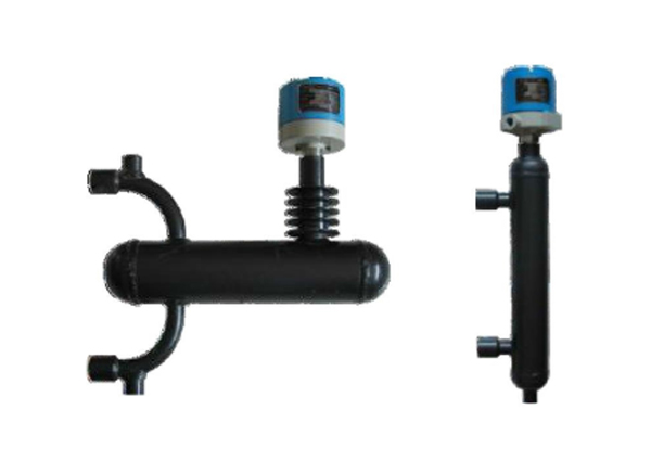
The 40H-5 level switches are designed for mounting externally on the process vessel and when used with isolation valves allows the switch to be isolated from the process. This feature is useful during start-up, or when maintenance is required. The chambers are offered with NPT, Socket weld and flanged connections as standard. The External cage can be welded type which makes is less prone to leakage, lighter in weight and consequently less expensive. Optionally Bolted type External cage is available which is comparatively heavier, but has an edge over former for ease in cleaning, inspection and has replacement feature of float Assemblies.
Principle of Operation
The operating principle provides for magnetic Switch action resulting from a change in liquid level, which moves a magnetic attraction sleeve into the field of an externally located magnet. This principle eliminates problems associated with flexing diaphragm seals, bellow seals, as well as coating problems encountered by probe type devices.
Specifications
| Pressure & Temperature Rating | Refer below |
| Attraction Sleeve | 410 Series Stainless Steel |
| Enclosing Tube | 304 SS |
| Electrical Connection | 3/4" NPT (Others optional) |
| Drain | 3/4" NPT (Standard) |
| Repeatability | +1.5 mm at S.G. 1 |
Cage Description (For 40H-5 Model)
Cage Type
Min. S.G.
Differential at S.G. 1
Pressure (Maximum)
Temperature (Maximum)
Cooling Fins
Expention LoopSealedFlanged54S54F0.6
Maximum 30 mm76 kg/cm2
0-150oC
Not RequiredNA60S 0.5160 kg/cm2NA74S74F0.770 kg/cm2150oC – 300oC
ProvideIf Required80S 0.6100 kg/cm2300oC – 350oCNA
Note: above 400°C Boiler Drum Level Gauge Provide
Chamber Style

LIST OF PROCESS CONTROL INSTRUMENTS
| SN | Item | SN | Item |
|---|---|---|---|
Liquid Level Switches |
Level Gauges |
||
| 1 | Float Operated | 1 | Reflex Type |
| 2 | Displacer Type | 2 | Transparent Type |
| 3 | Rotary PaddleType | 3 | Tubular Type |
| 4 | RF Type | 4 | Float and Board |
| 5 | Conductivity Type | 5 | Float and Dial |
| 6 | Electronic Conductivity Type | 6 | Gear Type Level Gauge |
| 7 | Capacitance Type |
Level Transmitters |
|
| 8 | Balloon Type | 1 | Smart Displacement Type Level Transmitter (DGMS Approved) |
| 9 | Vibrating Rod/Fork Type | 2 | Bi-Color Magnetic Level Indicator/ Transmitter |
Flow Switch |
3 | Non-Contact Radar Level Transmitter | |
| 1 | Flapper Type (DGMS Approved) | 4 | Guided Wave Radar Level Transmitter |
| 2 | Plug Type (DGMS Approved) | 5 | Differential Pressure Flow Transmitter |
Flow Indicator |
6 | Differential Pressure Level Transmitter | |
| 1 | Rota meter | 7 | Pressure Transmitter |
| 2 | Side Flow Indicator | 8 | Ultrasonic Type Level Transmitters |
Valve Positioner & Accessories |
9 | Temperature Transmitter | |
| 1 | Smart Positioner | 10 | Gear Type Level Gauge Transmitters |
| 2 | Electro Pneumatic Positioner |
Pneumatic Level Instrument for Oil Industries |
|
| 3 | Pneumatic-Pneumatic Positioner | 1 | Interface Level Controller |
| 4 | Positioner Transmitter | 2 | Level Controller Flex (Tube) |
| 5 | Volume Booster | 3 | Micro Valve Level Controller |
| 6 | Air Filter Regulator | 4 | Level Controller (Internal Ball Float) |
| 7 | I/P Converter |
Instruments for Oil Production Industries |
|
| 8 | Pressure Controller | 1 | Safety System for Heaters |
GAS ANALYSERS (EMISSION) |
2 | Low Temperature Shut Down Switch for Pilot Burner | |
| 1 | Nox | 3 | Self-Operated Temperature Controller/Regulator with Mercury filled |
| 2 | Sox | 4 | Element |
| 3 | Co | 5 | Electronic Remote Igniter (Weather Proof/ Explosion Proof) |
| 4 | Co2 | 6 | Flare Pilot Burner |
| 5 | O2 | 7 | Air Gas Pressure Regulators |
| 6 | H2 | 8 | Time Cycle Controller (DGMS Approved) |
| 7 | HF |
WATER ANALYSERS |
|
| 8 | HCL | 1 | BOD |
| 9 | H2S | 2 | KOD |
| 10 | O3 | TOC | |
| 11 | NH3 | 4 | ISS |
| 12 | CL2 | 5 | TDS |
Ambient Air Quality Monitoring System |
6 | DO | |
| 1 | SO2, NO2, NO, CO, CO2, NH3, H2S, O3, O2, PM 2.5, PM 10 | 7 | PH |
Wireless Instruments |
8 | ORP | |
| 1 | GSM | 9 | CONDUCTIVITY |
| 2 | GPRS | 10 | TURBIDITY |
| 3 | 2.4/5.8 GHZ | 11 | ARSENIC |
| 4 | Real Time Online Monitoring System | 12 | AMMONIA |
| 14 | Water Hardness Analyzer | ||
| 15 | Silica Analyzer | ||
| 16 | Metal Analyzer | ||
Other Instruments |
|||
| 1 | Electronic Time Cycle Controller | ||
| 2 | Silo Material Blockage Removal Machine | ||
| 3 | Plunger Lift Components | ||
| 4 | Portable Corrosion & Hydrogen Flux Monitor | ||
