Ban Level Gauge Reflex type
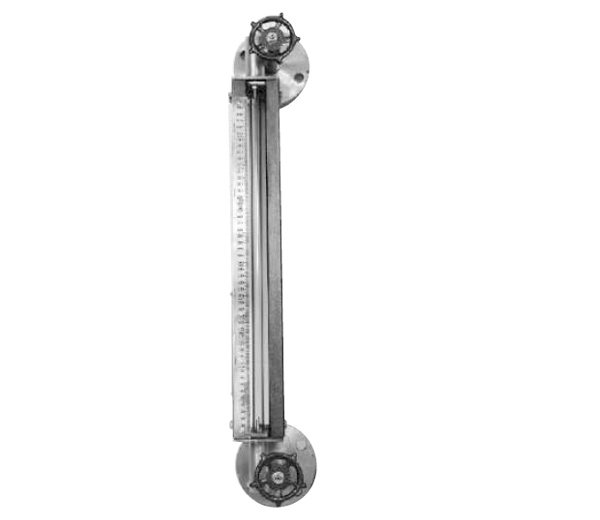
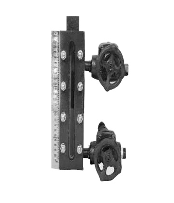
GTLG SERIES GLASS TUBE LIQUID LEVEL GAUGE (Tubular Level Gauge): TOP & BOTTOM CONNECTION ORIENTATION /SIDE-SIDE MOUNTED TYPE.
Simplest design, offers accurate reading in water, chemicals, petroleum products and corrosive liquid Level measurement.
Standard visible length is always less than C-C distance. The maximum operating pressure range is 10 kg/cm and maximum operating temperature range is 300 °C. Special featured valves with ball check arrangement. Isolation valves prevent the spillage of medium in the air. MS / SS-Tie rods/ or C-Channel protects the Glass Tube from any mechanical impact.
SS scale fitted adjacent to glass tube offers local reading effectively.
Fix and relax design in level metering. Vent/Drain provision – Plug or Valve.
Pair of Valves
VA-2500: Offset with integral bonnet and Ball check arrangement-pair of Isolation Valves.
Specifications
| C/C Distance | Up to1500mm in single glass tube, if more please contact factory |
| Materials | Carbon steel, Stainless steel, PP as standard |
| Glass | Borosil Tube of 12mm-19mm dia |
| Glass Protector | MS/SS304 Tie rods / C-Channel |
| Valves | Auto – shut – off ball check |
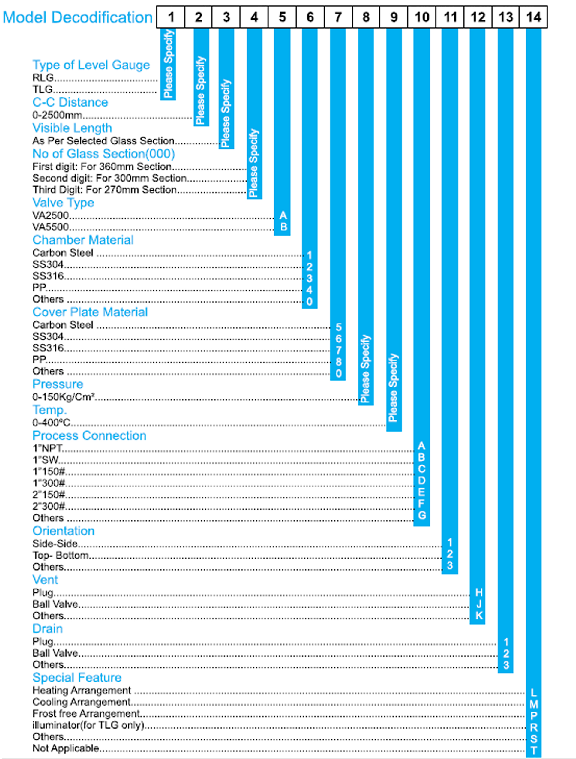
Ordering Information (TUBULAR LEVEL GAUGE)
Specifications |
|
|---|---|
| GTLG | Glass Tube Level Gauge |
| 0000 | CC-Distance in mm |
| 0000 | Visible Length in mm |
| VA2500 | Pair of Valves |
| MOC | CS – A SS304 – B SS316 – C PP -D Others – 0 |
| GTLG-mm – mm – VA 2500 – MOC | |
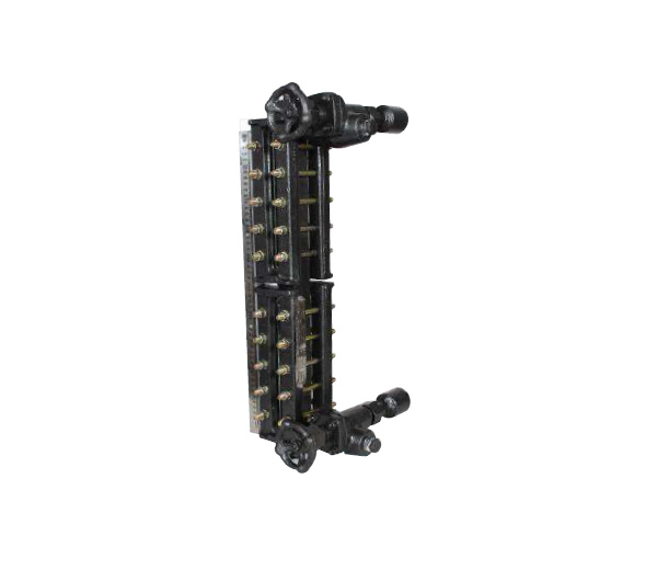
RLG SERIES-GLASS PLATE LIQUID LEVEL GAUGE (Reflex Level Gauge)
These gauges are used for measuring the level in a vessel. These can be used for maximum pressure of upto 150kg/cm and a maximum temperature of 400° C. Constructional features include upto 2.5 metre single piece construction with multiple glasses between process connections. A pair of auto shut off ball check valves in.
Working Principle
The principle of Reflex Level Gauges is based on the difference in the refractive principle of liquid and vapour. The liquid column is contained within the recess of the liquid chamber behind the sight glass which is clamped to the gauge body. The sight glass has prismatic right-angled grooves on the side facing the liquid and vapor space. Light rays entering from outside the gauge are either absorbed or reflected depending upon whether they enter the liquid or vapour space. When the ray of light encounters the surface of one of the grooves in the vapor space, it is the opposite surface of the groove and from there, totally reflected back to the direction of observation. Thus, vapour space appears as silvery white. When the light ray encounters the surface of the grooves in the liquid space, it is totally absorbed thereby the liquid behind the glass appear black.
| Max. Temperature | 400°C |
| Max. Pressure | 150kg/cm |
| Pair of Valves | VA-2500 Offset, integral bonnet with ball check arrangement VA-5500 Offset design, bolted bonnet, renewable seats and ball |
Note: In multi sections, the gap between two section is upto 5mm.
: Indication Assembly can be rotated by 360° to get unhindered view of liquid from
Specifications
| C/C Distance | Up to 100"; single piece liquid chamber. |
| Chamber | CS, SS-304, SS316, PP |
| Cover plate | CS, SS-304, SS-316, PP |
| Flange | CS, SS-304, SS-316, PP |
| Valves | CS, SS-304, SS-316, PP |
| Glass | Toughened Borosilicate |
| Connections | Flanged, Screwed or Socked weld. |
| Gauge Valve | Auto-Shut-off ball check, off-set pattern, Bolted or Screwed bonnet. |
| Drain/Vent Valve | Ball Type |
| Options | Anti-frost extension for low temperature service. Heating / Cooling arrangements |
| Glass Sizes | a) 340 x 30 x 17 mm b) 280 x 30 x 17 mm c) 250 x 30 x 17 mm |
TLG SERIES-TRANSPARENT GLASS TYPE LIQUID LEVEL GAUGE
These gauges are used for measuring the level in a vessel. These can be used for maximum pressure of upto 150 kg/cm and a maximum temperature of 400° C. Constructional features include 2.5 metre single piece construction with multiple glasses between process connections. A pair of auto shut off ball check valves in material of construction Carbon Steel or Stainless Steel and Polypropylene as optional.
Working Principle
Transparent Level Gauges employ two transparent glasses and a liquid chamber. The liquid level is indicated as a result of difference in the transparent properties of the two media. For water / steam applications, an illuminator is mounted on the rear side of the gauge with its light rays deflected upward into the water column. This enable the observer to see the illuminated surface of the water as the light rays impinge on the surface of separation between water and steam are reflected back to the eye of the observer. For High Temperature application mica shield is used.
Specifications
| C/C Distance | Up to 100"; single piece liquid chamber. |
| Chamber | CS, SS-304, SS316, PP |
| Cover plate | CS, SS-304, SS-316, PP |
| Flange | CS, SS-304, SS-316, PP |
| Valves | CS, SS-304, SS-316, PP |
| Glass | Toughened Borosilicate |
| Connections | Flanged, Screwed or Socked weld. |
| Gauge Valve | Auto-Shut-off ball check, off-set pattern, Bolted or Screwed bonnet. |
| Drain/Vent Valve | Ball Type |
| Illuminator | 230/110VAC 50/60 Hz |
| Glass Sizes | a) 340 x 30 x 17 mm b) 280 x 30 x 17 mm c) 250 x 30 x 17 mm |
Note: In multi sections, the gap between two section is upto 5mm.
: Indication Assembly can be rotated by 360° to get unhindered view of liquid from any angle.
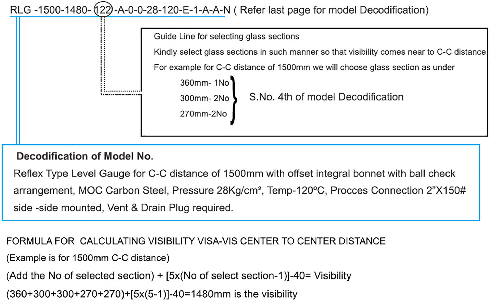
Guide to Arrive at Visible Length (Reflex / Transparent Types)
Gauges are assembled with multiglass assembled sections. Below are the details of the glass length/sectional length & visible portion.
| Glass Section Length | 360 mm | 300 mm | 270 mm |
| Glass Length | 340 mm | 280 mm | 250 mm |
| Visible Length | 320 mm | 260 mm | 230 mm |
